In Part 1 we covered the FWD swap parts needed, the donor cars to look for, and other mechanical considerations (fuel, exhaust, brackets). In Part 2 below, we'll cover tips and tricks for pulling the 4100 and installing the new Olds block. And finally, in Part 3, it's the Electrical Swap Guide to get all your warning lights and accessories working again.
|
1. HT4100 Engine Removal Procedure |
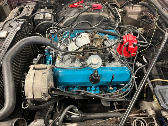 |
Alright, here we go! This isn't too bad a job, just take your time and plan ahead and everything should go smoothly. If the car's outside, I leave the hood on and disconnect everything I can until it's time to actually pull the engine, and I wait to pull the heater/radiator hoses until AFTER I'm done crawling around underneath unbolting things so I'm not laying in antifreeze. Also... DO NOT CUT ANY ENGINE WIRING.
| Step 1: Remove battery and disconnect the positive cable from the fender-mounted terminal box (starter cable is siamesed at the battery terminal). Remove the fender to firewall braces and air cleaner. Remove & retain the coolant reservoir. Disconnect the ground straps: One at engine rear, one on passenger side to frame. Slip batt cable out of clip on frame near pass side exhaust manifold. |
|
Step 2: Jack up car and unbolt the output shaft flanges from the inboard CV joints/axles. Some Eldos use standard hex-head 15mm bolts, others may require a 12-point socket. The toughest part is keeping the shaft(s) from rotating while you're trying to break the bolts free. Worst case, make sure the trans is in park, jack up one side of the car to a sufficient height you can slide under (making sure to lower it onto a jackstand first). Then run the jack to the other side of the car. With that one tire making contact with the ground, break free as many bolts as you can reach on both sides. Then pump that jack up a few times, give the tire half a turn, lower back down, and do it again. If the hubcaps are off, you can slip a breaker bar into one of the rim slots and rotate until the caliper stops it. Repeat as needed until all bolts are out. |
|
Step 3: Exhaust: 1. Unbolt or cut the exhaust just forward of the cat converter (you will not be reusing these downpipes). 2. Unbolt or cut the exhaust on the driver's side where it meets the manifold; there is sufficient room to get a sawzall in there. 3. Finally, you need to get the exhaust downpipe free of the manifold on the passenger side as it'll hang up on the trans mount, but that area is close quarters. I found it was possible to make a sawzall cut from under the car, as far up the downpipe as practical. Then once the engine was partially out, access to cut at the manifold flange was a piece of cake. Obviously, the down-pipe / y-pipe will not be re-used. If the air injection line to the cat converter is still present, cut it off, too. |
| Step 4: Unbolt the front engine mounts by removing the two “90Nm” (18mm) nuts from the engine mount studs as shown in the diagram below. While you're down there, remove the two 10mm bolts securing the bottom of the fan shroud. |
|
Step 5: Disconnect the shift linkage from the column, and at the trans (secured with cotter pins); remove the linkages but leave the bracket on the engine if you wish. Disconnect the two bulkhead connectors from the firewall: Using a 1/4" ratchet with short extension, and a 1/4" socket, loosen the screw in the center of the top "round" environmental connector and it should pull right out. The lower connector is attached the same way, and is technically 2 connectors in one assembly- one is the engine harness, the other is for under hood components separate from the engine. After you've disconnected this assembly from the firewall, unclip the one connector (clips on each side) and separate. Finally, depending on the year, you may have a couple stragglers to unplug, such as the "low vacuum" switch on the brake booster, the connector for the charcoal canister purge valve, and the adjacent connector that leads to the external temp sensor in the front grille. |
|
Step 6: Rear transmission mounts, this is how I do it: Remove the single long bolt through the center of the donut mount on each side. Don't worry, welded tabs will prevent the engine from dropping. Next, support the trans pan with a jack and piece of wood. Apply a little pressure. Now, on the passenger side, remove the three bolts going from the trans bracket into the trans. On the driver's side, remove the three bolts threading into the side of the trans from the bracket. You may need to use a box wrench and pipe to break one or more loose, and may need to work from both top and bottom. If any are blocked, simply jack the trans up an inch or two to get access. When through, leave the jack under the trans for support. |
| Step 7: Now it's time to work top-side: Remove the radiator retainer plate and unbolt fan shroud from header. Remove self tappers securing the power steering reservoir to the shroud. Remove top half of fan shroud (the two halves are attached with small self tapping screws on each side). Unbolt and remove the fan/clutch assm. Disconnect and remove the alternator. Disconnect (or cut) the accel cable. Disconnect the speedometer cable at trans. Cut/disconnect vacuum lines and disconnect fuel supply and return lines at back of TBI. Remove any clamps securing these lines to get it free of the engine/trans. Disconnect or cut the power steering pump to steering gear hoses. The rubber evap hose is also in this area; carefully disconnect it. Unbolt the AC compressor and flip it aside to rest on the inner fender so that you don't have to break open the AC system. Or if you're not re-using the AC parts, you can leave the compressor in place and disconnect the lines on the backside. You may also find it advantageous to remove the AC drier where it enters the heater box. Use a backup wrench so you don't damage the evaporator. |
| Step 8: With a flare wrench, disconnect the trans cooler lines at the radiator. Some E/K's also have an oil cooler, so disconnect or cut these lines at the rad as well. If you're planning on re-using the trans cooler hard lines, I recommend disconnecting these at the trans and removing them to prevent damage. These lines are tucked into a large clip on the passenger side of the engine. Be sure to plug the ports on the trans to keep debris from entering. Cut/disconnect heater hoses and radiator hoses (prepare for a mess). Remove the radiator and lower shroud. Retain the vac operated heater valve for later. |
|
Step 9: Final Check: Make sure everything physically attached to the engine/trans is disconnected. Remove the hood and set aside. If you chose option 2 above for the trans mounts, place a jack with block under the trans pan and -now- remove those 3 bolts from each side that you broke free, applying enough support under the pan so that they come out without binding. Chain up the engine, and using a leveler, put more lift on the front than rear to get the front studs out of the crossmember and get the final drive cover to clear the steering link. If you chose option 1, then you'll need to get the rear trans brackets high enough to clear the trans mount "ears" without binding the rear chain cover on the firewall. Once the rear of the trans is free and the front studs are out, removal is straightforward. |
*If you need to swap out/repair your power antenna, now is the time to do it as the passenger side hood hinge has to be removed to get the antenna out. See the Tech Section for details.
 |
 |
|
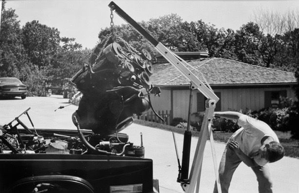
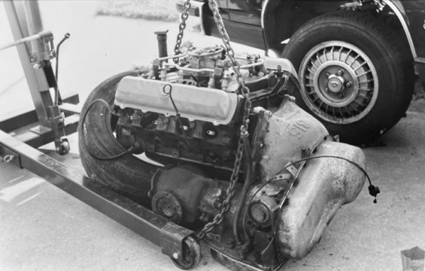
| Front & Rear brackets securing engine & trans- See Buick Dwg Above | A high angle of attack is a must for removal/install. | Rear brackets are visible here; life is easier if removed before installation |
2. Engine Installation Pointers:
| Torque Values | |
| Output Shafts to Drive Axles (use threadlocker) | 60 ft-lb |
| Starter Bolts (M12) | 31 ft-lb |
| Transmission Pan | 7-10 ft-lb |
| Final Drive to Transmission (M10) | 30 ft-lb |
| Output Shaft Bracket to Block (7/16") | 50 ft-lb |
| Torque Converter to Flex Plate (use threadlocker) | 35 ft-lb |
- With the HT4100 out of the car, you'll want to carefully remove the two engine harnesses to reuse with the new engine. Quite a lot obviously won't get re-connected, and wires can be stagger-cut, taped/shrink tubed to prevent shorting. But don't do anything just yet, you might want to re-use some of that wiring for gauges & lights. Please see the Electrical Swap Section section for full details.
- Ground Strap: There should be two: one at the rear of the engine and one on the passenger side near the battery. If yours have gone missing, be sure to replace them. Otherwise, currents will find their own path back to the frame, either through sensitive electronics, or even engine bearings, and resistance can affect aftermarket gauge readings.
- The HT4100 cars use metric steering gears; see info above in Section 2.
- If your trans cooler lines are shot, new ones can be made from 60" off the shelf steel (brake) line. One is exactly 60", the other a couple inches shorter, but there's enough 'play' that 60" can work, avoiding any cutting or flaring.
- Before you even think about putting the THM325-4L back in the car, there are a few things you should do. First, order a Transgo SK-325-4L kit and follow the instructions to-the-letter. This will improve all of the factory deficiencies, improve shift quality, and give your trans more life, especially with a more powerful engine. Even if you decide to do a basic rebuild, include this kit in your plans.
- You might want to replace the RH output shaft bracket bearing, but here's the rub...Timken 6206-2RS is the "official sub". OD is perfect, but I have yet to get the ID to fit the original shaft. Some have gone as far as having a machine shop turn the diameter down to fit. AFAIK, there is no direct replacement. Either way, at least make sure your old one is in good shape.
- When you go to install the new engine/trans package, remove the rear transmission mount brackets from the trans. Set your leveler so that the trans chain cover tucks in under the firewall at a steep angle, then support the rear of the trans with a jack and wood block. Lower the front down so the studs drop into the cross-member, then jack the rear of the trans up to allow reinstallation of the rear u-brackets. Doing it this way will save hours of frustration. The driver side bracket doesn't have enough clearance for a ratchet, but a Gearwrench fits, and you can jack that side up as needed to get the bolts in and started.
This is also a good time to replace any seals, such as:
- Front Diff Output Seals – Timken TM3907 is a good sub for these.
- Torque Converter Seal, Dipstick Tube seal (ATP brand SO-35), Shift Shaft o-ring, TV cable.
- New trans filter with o-ring, and add a small magnet square to the pan to catch clutch material.
-> One expert claims torque converter drainback was an early issue on these; the official fix was a filter with a check valve in it, but I guess not all replacements take
this into consideration. - "Do as I say, and not as I do" and add a drain plug to make life easier down the road.
If you changed transmissions or final drives, this would be a good time to sit down and recalculate your speedometer error. Different rims/tires will also affect this. Depending how far off you are, a road test with a GPS speed app on your phone can help dial in error. Remember, GM made quite a few different speedo output gear ratio options that will drop into your trans; if you can't find exactly what you need, you should be able to get pretty darn close with a speedometer cable ratio change gearbox and a matching trans gear. Lots of flexibility there.
Depending how handy you are, you could also expand the speedo face to something beyond 85MPH, printed on good quality vinyl or UV-stable backer. See the Speedometer Swap Page for more.
When it comes to Olds engines, I'm far from an expert, but having just gone through the rebuild process, perhaps the following will be helpful. Especially since most machine shops seem to only be familiar with Chevy and Ford mills.
- The cup plugs in the heads (2 per) are 1-1/4 and should be the 'deep' type. Melling MPC-18B is a perfect fit.
- At the rear of the block is a 29/32" cup plug. This allows access to an internal pipe plug at the end of the driver-side oil gallery. Both should be removed before hot-tanking. The pipe plug (if original) takes a 5/16" square head drive. You can grind down a 3/8" extension, or pick up an 8mm "Oil Drain Plug" socket which I was able to find locally a lot easier than a 5/16" one. The pipe plug is special in that it has a 0.040" hole in the center for oiling the distributor drive. You'll want to make sure you've got daylight there and re-use it.
- At the front of the block, behind the cam gear, are two threaded plugs; they look the same but are different sizes. They are not NPT. Clean and re-use them. One also has a 0.040" hole for oiling the timing chain. When you first pull the front cover, you should see an oil slinger on the crank. Sometimes these go missing.
- My Fel-Pro gasket set came with a rope seal for the rear main; apparently most sets do. A Ford 292 Y-block neoprene seal is a perfect fit for the SBO. Some Olds sellers offer a neoprene/rubber seal as well, but these are just the Ford seal with a healthy markup.
- Push Rods..... when you walk into a parts store, or pull up Rock Auto, the stock length is listed as 8.234". My '77 & '79 shop manuals list stock length at 8.265". To complicate matters, Olds replacement camshafts (even if stock spec), are usually ground on reduced-base circle blanks. Edelbrock suggests using big block Chevy intake pushrods which are ~0.030" longer. The safest thing to do is check lifter pre-load. I used Sealed Power RP-3182 which are indeed BBC intake PR's, and had pre-load in the 0.030" to 0.040" range. The originals were closer to 0.010" with the new cam.
- I have been told the Edelbrock Olds cams are actually made by Melling and re-boxed with a markup. Unfortunately, it was all I could find available at the time as many shops & online sources no longer stock hard inventory and are simply middle-men .
- My intake manifold only had one threaded port for a temp gauge, but it did have an adjacent flat which was easy enough to drill and tap for a second sensor. This did the trick.
- Olds factory head gaskets are in the neighborhood of 0.017" thick, though some claim they changed in the late '70s. If yours is this thickness, be aware that the aftermarket replacements are 2x as thick and will drop your compression. There are a couple companies (like SCE) making shim stock Olds gaskets that are close to the original spec when compressed, but they're a little spendy.
- If you can get your hands on an NOS dipstick tube, do it. The only other alternative are the aftermarket chrome jobs...I'm told these will require filing of the two crush ribs to fit the block properly, and at least one brand is too loose. I don't believe the stock dipstick will work with these, either.
- While 307-centric, this prehistoric Tripod page has good info on heads, ignition, trans info, and other Olds tips.
And Now...The Conclusion: Electrical Swap Section
Return to Main Page Comments? Corrections? Contact Webmaster Cory Heisterkamp 2022